The K1YPP Magnetic Loop Antenna
The K1YPP Magnetic Loop Antenna
Note to my readers of this blog: I’ve decided to expand the blog to include various other interests I have. Up until now everything that I’ve posted has been strictly about writing and author related topics. Since I have varied interests, such as ham radio, bicycling and hiking, for example, I’ll be including topics related to those fields. This post is about an antenna that I have been researching for several years for amateur radio (also known as “ham radio”). There is a Youtube video of this project at: https://www.youtube.com/watch?v=B-tYtbTts0s
I’ve been living in a home owner’s association (HOA) for some time now and have been on the air as an amateur radio operator. There are challenges, but one can get on the air in an HOA.
I’ve been experimenting with Magnetic Loop Antennas, (MLA’s) for years. They are small, light-weight, and have excellent local electrical noise rejection. For years I had avoided building one because most of the designs involved a daunting array of expensive vacuum capacitors, fancy welding and brazing, special low-resistance materials, etc.
My new antenna would have to meet three requirements:
-
Cost $50.00 or less (excluding remote tuning devices, such as motors, hydraulics, etc.).
-
Cover 40, 30 and 20 meters.
-
Have a minimum power limit of 30 watts ( for CW and PSK31).
The primary challenge is to keep resistive losses to a minimum. Many MLA designs use large diameter copper pipes and silver-soldered joints. Builders favor vacuum capacitors or butterfly capacitors that have no electrical contacts or brushes because the contacts will overheat.
Based on the calculations on Steve Yates’ (AA5TB) web page Small Transmitting Loop Antennas, I settled on a four-foot diameter for the desired frequencies. My initial prototypes used folded aluminum foil on PVC pipe, but the foil was too difficult to work with, especially if outdoors in a windy location. I then tried aluminum weather-seal tape and found success.
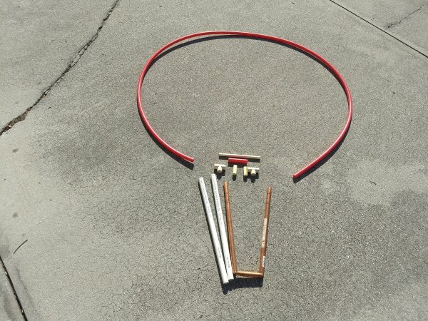
Parts before assembly. The PVC-to-CPVC adapters are not shown.
I formed the loop with 12 feet of the flexible ¾ inch Sharkbite PVC and used two straight pieces of a larger ¾ inch diameter PVC (Lowes # 23990) to form the capacitor. ¾ Inch copper tubing fits nicely inside this particular PVC tubing, without too much “slop.” I used a continuous piece of aluminum foil tape (2 inch width) spiral wrapped around the loop and down along the two tubes that formed the “capacitor.” The tape I used was made by Nashua Corp, and has a sticky back with a blue plastic cover over the glue. I didn’t remove the plastic, it made construction easier and less messy. The only soldering is the SO-239 coaxial connector. In the first prototype, I wrapped folded aluminum foil in a spiral around the loop and then around the vertical tubes, but the spiral proved to be problematic for the capacitor. The contacts between the spiral as it wrapped down the vertical tube provided contact resistance and the resulting high currents affected the SWR. I found a solution by leaving a gap in the spiral wraps so that the foil did not overlap or touch.
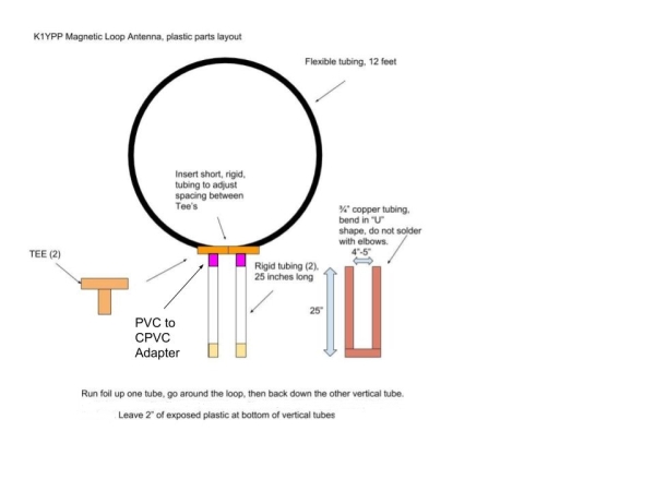
The capacitor is actually a form of “Butterfly” capacitor, formed by the outer foil on one tube, the “trombone” copper tubing, and the foil around adjacent tube. When purchasing the vertical tubing, make certain the 3/4 inch copper tubing will fit inside the plastic tubing. There are many variations so careful selection is necessary to insure the copper will slide inside the plastic tubing. To adapt the CPVC “TEE” fitting to the vertical tubes, I used a PVC-to-CPVC adapter (Lowes #65322) with a small section of Sharkbite tubing inside. The parts are all held together with some self-tapping screws, glue isn’t needed. With the dimensions used, the capacitor measures about 200 µF per foot, giving a total of about 100 µF/foot for the two legs being in series. The 40 M band needs about 160 µF of capacitance, so the legs have to be about 22 inches. The good news is, since the capacitor goes through two pieces of plastic tubing, the voltage rating doubles. PVC is rated at about 140 kV/CM, so this configuration should be good for about 20 kV.
Tuning the capacitor is a matter of sliding the “U” shaped copper tubing “trombone” up or down in the capacitor to achieve resonance.
I made a small feeder loop to couple to the main loop. I soldered a SO-239 coaxial connector to common household #12 electrical wire, about a foot in diameter. I then attached the small loop at the top of the MLA and coupled it tightly to the main loop. Using an antenna analyzer, I adjusted for best SWR. This proved easier than anticipated. A loop about one-fourth to one-fifth the diameter of the main loop worked best.
Construction
Simply cut the plastic pieces to length and plug them together. You can also use duct tape during the wrapping process to hold the aluminum in place. To form the U-shaped “trombone,” notch the copper pipe with a hacksaw or “crush” it in a vice, and then bend it to ninety degrees. For a more “finished” look, one can heat the copper to red-hot, then let it cool slowly. Then, fill it with sand or salt, then bend it over a round surface. Look around on Youtube for various methods.
Wrap the foil starting at the bottom of one capacitor tube, follow up around the loop and then down the other capacitor tube. Keep a small gap between windings on the capacitor tube, about a 1/4” is sufficient.
After wrapping the foil, mount the small loop with duct tape or tie wraps, and then insert the “trombone” copper tubing. The antenna is now ready for testing.
Testing
With an antenna analyzer
I used an MFJ antenna analyzer for the testing phase. If one is not available, see the instructions below for testing with a transmitter and receiver.
To test, push the “trombone” all the way into the capacitor tubes. Search above and below the expected frequency to find a dramatic dip in SWR. The coupling loop may need adjustment to get the lowest SWR. If the dip is below the 40 M band, withdraw the “trombone” until it resonates at the bottom of the band. If it is too high in frequency with the “trombone” inserted all the way, then there is not enough capacitance. Either the aluminum is not tightly wrapped around the capacitor tubes or the plastic tubes are too short.
Once you are satisfied with the adjustment, mark the copper tubing with a grease pencil to show where the 40 M band is.
Next, pull the “trombone” out a few inches and then find the resonant location for the 30 M band. Finally, do the same for the 20 M band. If your main loop is about 44 inches in diameter, there is a good chance it will work on 17 meters as well.
Using a transmitter and receiver
Use a VERY low power transmitter and an SWR meter. Caution: the currents and voltages around the capacitor section of the antenna are extreme. Even a few watts will cause serious RF burns. Be careful.
Move the “trombone” in fully and then tune around with the receiver until noting a marked increase in noise. This is where the antenna is resonant. Slide the “trombone” until it is resonant at the desired portion of the 40 M band and then apply a small amount of power from the transmitter and check the SWR. If the small loop needs adjusting, turn off the transmitter and cautiously adjust until the antenna is working as desired. Mark the copper tubing to indicate the band.
On The Air
Once you have tuned the antenna to satisfaction, mount it where no one can touch it when transmitting. With a loop diameter of 48 inches, the bandwidth is about 129 kHz on 40 M, and 293 kHz on 20 M. This is wider than many of the commercial MLA’s, but I was more concerned about efficiency and bandwidth. A larger loop is more efficient. A smaller loop can be better at rejecting local noise, but I found the combination here to be more than adequate. A wider bandwidth eliminates constantly re-tuning the antenna.
At a future date, I will post something on how to build a stepper motor driver for this antenna. Look around the Internet for existing designs.
As for maximum power, the antenna has consistently handled 100 watts on CW without heating or voltage breakdown. Since I only tested with 100 watts, it isn’t clear what the upper limit might be.
As for performance, that is a difficult thing to judge. My experience indicates that this antenna on 40 Meters performs almost as well as a G5RV at 35 feet, and as well as the G5RV on the higher bands.
Did the antenna meet the design goals?
My original design goals were modest: the antenna needed to cost under $50.00, operate on three bands, and handle 30 watts. Yes. In fact, it exceeded all the goals, it:
-
Costs under $20.00 to build (not counting a remote tuning mechanism).
-
Operates on 40, 30 and 20 M. One version, a slightly smaller loop (44 inches), also functions on 17 M.
-
Runs well at 100 watts. The upper power limit is yet unproven.
This antenna is impressive. Over the last several months, I have worked many DX stations and maintained reliable communications in long-winded rag-chewing sessions. Not only is it a pleasure to use, it has been a rewarding homebrewing experience.
A 20 meter through 10 meter version of this antenna is possible. I have one where the main loop is 32 inches in diameter (81 cm) and the capacitor tubes are 20 inches (51 cm). The capacitor tubes can use PVC pipe, such as the straight version of the 3/4 inch Sharkbite product and 1/2 inch copper tubing.
73 de K1YPP
Partial parts list
|
Note: Lowes will ship to store if ordered on line |
|||
|
Item |
Quantity |
Length |
Comments |
|
Charlotte Pipe ¾ inch x 10 ft, 200PSI PVC pipe |
1 |
10 feet |
Lowes #23990 |
|
Sharkbite PEX flexible tubing |
– |
13 feet |
Cut short pieces to connect Tee’s Lowes #998500 |
|
¾ inch copper tubing, type M |
1 |
5 feet |
Confirm it fits in capacitor PVC tubing, Lowes #23792 |
|
¾ inch CPVC Tee |
2 |
– |
Sharkbite should fit snugly, Lowes #23760 |
|
¾ inch CPVC to PVC adapter |
2 |
– |
Couples Tee to capacitor PVC, Lowes #65322 |
|
Aluminum tape, 2 inch x 10 yards |
1 |
30 feet |
Plastic backed sticky tape Nashua Corp, #322 |


Dennis, Thanks very much for this. I am considering building a mag-loop and you have one of the best practical designs that I have seen !! 73- Bill K4WWD
Great Design! I’ve sent a citation to Jim VK5TR, of AHARS, who’s been making Loop Ant’s for years. I’ve been looking for a simple plan, myself, & I’m sure this is it. ;~)
(It’s like Safe New Liquid-Fuel, Molten Salt Reactors – compared to solid Fuel-Rod dinosaurs of the previous LWR/PWR era (aka “Fukushima-era”). Cf IAEA’s free: “SMR-book_2018.pdf”
A Very Elegant Solution! Thanks for Sharing it.
Jim was quick to reply, having used Trombone Capacitors earlier:
“If you get [WIA’s] AR magazine then you will know I published an article entitled “the Plastic Fantastic” [in Feb. 2017 issue]. If not then I have attached the article to this email anyway.
Said antenna uses the trombone capacitor approach and probably represents the minimum standard of construction you can get away with for a mag loop. in Australia. (this of course is not the case in the States where there are far more close together HF stations than here and where even the most awful antenna has a chance of being heard).
Unhappily the YouTube construct falls substantially below this :-(. It will work on receive, but will be singularly appalling on transmit. It may even be singularly appalling on receive also.
The problem is two fold:
First, no loop will efficiently cover three bands- period. A brief study will show that the loop circumference should be between 0.1 and 0.2 wavelengths. (at 0.25 wavelengths the tuning capacitor value required is zero). At 0.1 wavelengths in an efficient loop structure the transmit efficiency will be of the order of 10% rising rapidly to around 85% (of the efficiency of a dipole ) at 0.2 wavelengths.
Next, for efficiency, it is vitally important that the loop conductor material is of very low resistivity and of at least square but preferentially circular shape. The aluminium tape used in the video is a disaster. Flat material such as this tape or say flat copper strip has a much higher RF resistance than the same material formed into a circular tube because HF RF current bunches on a flat strip around the two edges of the strip with very little RF current flowing on either of the two flat surfaces.
Sorry to be so damning, but that is the unhappy truth. Constructing a RF resonant circuit with a Q around 1000 is not a task in which the slightest short cuts can be made. The Plastic Fantastic had a Q of around 450 and can only be described as “adequate” :-(. ”
( If I find an eMail address for you, I can send Jim’s 2017 article. If you’d like to facilitate this,
eMail me via: MSR-Th90@ProtonMail.CH -or- Liquid.Fuel.Nuclear@ProtonMail.CH )
For the love of God, it supposed to be an expensive antenna experiment. Not a Saturn V.
I personally may give it a crack. What’s the worst that can happen? Good article.
Hi,
I am a bit unclear about this. I’m completely new to building antennas, so I don’t understand how the small loop connects. Does it directly connect to the tape at the top? I like the design, and I attempted to build my own, it just didn’t quite work out how I expected, but that’s mostly because of my lack of experience making these.
Does it make a difference i the copper tube isn’t one complete piece? I had a mishap while trying to put the curve in my tube and it kinked. so i just broke it off and moved on.
Thanks!
I enjoyed the video and I’m looking forward to making this cheap antenna work.
KK4VWC
The small loop is very close to the main loop, but doesn’t actually touch it. I have about a 1/4″ space between them. As for the broken tubing, it can be soldered together and will work, but there will be some small loss in the soldered connection, but go for it! One trick that improves SWR is make the feed loop more of an oval shape, rather than round. Experiment with that.
I’ve also kinked some of that copper now and then. One trick to bending it is to first heat the area that is to be bent, and heat it to red hot. Let it cool slowly and then you’ll find that the copper has gotten very soft and will bend better. Some people fill it (after it has cooled) with sand or salt and that help to keep it from kinking. If you live where there are freezing temperatures, you can fill it with water and let it freeze and then bend it, that also keeps it from kinking.
Good luck and keep us posted. I’ll listen for you once you’re on the air with it. de K1YPP
Been working on the mag loop. After some testing I realized that I was not careful with regard to wrapping the tape and leaving gaps. Also I discovered I severely scratched several spots. I am going to use a new tape but this time paying close attention to the wrapping gaps. I have been using 2 inch tape. I am wondering if using a small tape like 1 inch would work?
I’m certain that 1″ would work too, but I can’t say what the differences would be. It certainly would have somewhat higher loss, due to less copper, but I can’t imagine it would be too significant. Let me know how it works out.
I tried a design with five inch aluminium strip and a rotor blade of the same material set on the top. As the rotor lined up with the strip of the loop it was meant to work as a capacitor plate but it didn’t. The idea of a connection-free capacitor is great. No probs joining aluminium to copper and no problems at all with resistive joints. Really excellent bit of lateral thinking.